
Carbon Layup Design for Bike Frames
A frame's personality — how stiff it feels under power, how much road buzz reaches the saddle, how it survives a rock strike — is decided by the ply schedule long before anything is tested. This page explains what a layup actually consists of, what each part of a frame is designed to do, and how the priorities change between gravel, road, MTB and e-bike platforms.
What a carbon layup actually is
Carbon fibre is only strong along its length. A single ply of prepreg is therefore almost useless on its own — it is stiff in the fibre direction and weak across it. The engineering happens when plies are stacked at different angles so that the laminate as a whole resists loads from every direction.
A layup schedule defines four things for every zone of the frame: how many plies there are, what angle each ply sits at, in what order they are stacked, and how thick the resulting wall is. Change any one of those and the frame's stiffness, weight, damping and failure behaviour all change with it.
| Orientation | Primary contribution | Where it matters on a frame |
|---|---|---|
| 0° (along the tube axis) | Bending stiffness and longitudinal strength | Down tube and top tube, where pedalling and steering loads bend the frame |
| ±45° (off-axis) | Torsional stiffness — resistance to twisting | Down tube and bottom bracket area, where pedalling torque tries to twist the front triangle |
| 90° (hoop direction) | Crush resistance and hoop strength | Everywhere a tube is clamped or loaded radially: seat tube, bottom bracket shell, head tube, steerer |
| Surface and sacrificial plies | Impact resistance and finish | Outer layer of the down tube, chainstays and fork, where stone strike and cable rub happen |
Stiffness and comfort are not opposites — they are different axes
A frame can be torsionally very stiff at the bottom bracket while still allowing vertical deflection at the seat cluster. Racers want power to go into the rear wheel, not into twisting the frame, but they do not want every road imperfection delivered to the saddle. Good layup design separates those two behaviours instead of trading one against the other.
What each part of the frame is designed to do
A frame is not one laminate. It is a set of zones with different jobs, and the layup changes as you move through it. This is where a carbon frame stops being a material and starts being a design.
| Zone | Design priority | How the layup is tuned |
|---|---|---|
| Head tube and upper down tube | Steering precision and frontal impact survival | Hoop plies to resist ovalisation from the headset bearings, plus off-axis plies for the braking and impact loads that arrive through the fork. |
| Down tube | Torsional and bending stiffness — the main load path | The highest proportion of 0° and ±45° plies in the frame, with wall thickness tapering along the tube so material sits where the bending moment is greatest. |
| Bottom bracket shell | Power transfer without flex or creak | The most heavily reinforced junction. Multiple hoop plies plus off-axis reinforcement, and thick enough walls to be machined and faced without cutting into the structural laminate. |
| Chainstays | Lateral stiffness with controlled vertical flex | Flattened, vertically compliant sections combined with a stiff upper cap, so pedalling loads meet a stiff structure while the wheel can still track the ground. |
| Seat tube and seat cluster | Rider comfort | Deliberately thinner walls and fewer axial plies, so the seat tube can deflect slightly and take the edge off surface vibration without the frame feeling vague. |
| Seatstays | Shock absorption and rear-end compliance | Narrow, flattened profiles that flex vertically, plus a reinforced junction at the dropout where braking and drivetrain loads concentrate. |
| Fork crown and steerer | Impact and braking loads | The highest hoop-ply concentration on the bike. Fork failures are the most dangerous kind, so this zone is specified with the largest safety margin. |
The same layup logic, four different sets of priorities
This is the table that matters when you are choosing a platform. It is also the table that explains why a gravel frame is not just a road frame with wider tyres.
| Platform | Primary design goal | Secondary goal | What the layup gives up |
|---|---|---|---|
| Gravel | Impact and abrasion survival on unsealed surfaces | Compliance and vibration damping over long distances | Absolute minimum weight — impact plies and thicker exposed walls cost grams that a pure road frame does not carry. |
| Road | Stiffness per gram and aerodynamic efficiency | Torsional rigidity for sprinting and cornering | Impact tolerance. Road layups are optimised for smooth surfaces and are not designed to take repeated stone strike. |
| MTB | Survival of high impact and long-travel fork loads | Rear-end stiffness under standing efforts | Weight. Reinforced head tube, down tube and dropout junctions are unavoidable at this load level. |
| E-bike | Motor torque and system mass | Battery and motor mounting stiffness | Light weight. Continuous torque loading and a heavier total system require more material in the drive-side and motor-mount zones. |
Read together with our gravel frame technology page, which applies this table to the actual models in our range.
How a layup is proven, not just designed
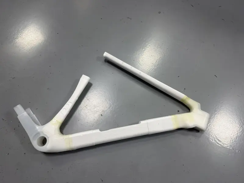
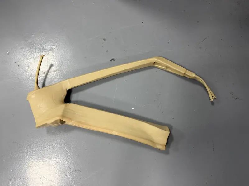
A ply schedule is a hypothesis until a frame built to that schedule has been tested. We treat layup changes the same way we treat geometry changes: they need evidence before they go into production.
- Ride targets translated into stiffness and weight numbers first
- Ply schedule built and checked against material data
- Sample frames built on the production line, not by hand in a lab
- Frames mounted and run on our fatigue and load rigs
- Frame weight and wall thickness checked against the schedule
- Any schedule revision re-tested rather than assumed equivalent
How frame stiffness is actually measured
Stiffness numbers are only comparable if everyone measures them the same way. The reference method is ISO 4210-6:2023 Annex E, which defines three measurements and the preload step that makes them repeatable.
| Measurement | Load applied | Reported in |
|---|---|---|
| Bottom bracket stiffness | 800 N applied vertically through the pedal axis and held for 1 minute, with the frame tilted 10° from vertical. Drive side first, then non-drive side. | N/mm |
| Fork lateral stiffness | 300 N applied along the fork axis and held for 1 minute, with the rear axle locked in a freely rotating mount. | N·m/degree |
| Seat tube stiffness | 100 kg hung 70 mm behind the seatpost axis, with a 750 mm vertical difference between the saddle position and the bottom bracket. | N·m/degree |
The method also specifies a preload: 20% of the test value applied for one minute and repeated, then released and displacement zeroed, before the full load is applied. Skip that step and the numbers are not repeatable between labs.
We will measure and report these three numbers for any platform on request, using the Annex E method, so a stiffness target written into a project brief can be verified on the finished frame instead of argued about.
Changing the layup does not usually require new tooling
Geometry changes need new moulds. Layup changes generally do not. For OEM projects this means a stiffness, weight or comfort target can often be met by revising the ply schedule on an existing platform, which is far faster and cheaper than developing new tooling. See OEM services for how those projects run.
Layup design FAQ
No. Stiffness only helps where the rider is putting energy into the frame — sprinting, climbing out of the saddle, high-torque efforts. Beyond a certain point, more stiffness does not make the rider faster; it just makes the frame harsher and heavier. For most riders on gravel and long-distance rides, the balance point sits well below the stiffness of a crit-racing frame.
Yes, and for heavier riders or loaded bikepacking use it is often the right call. A layup can be revised to add material in the high-stress junctions without changing the geometry or the tooling. Tell us the system weight, terrain and expected load and we will recommend a schedule. Send us the details.
By separating the two behaviours. Torsional stiffness is kept high through the down tube and bottom bracket, because that is where pedalling energy is lost. Vertical compliance is introduced at the seat cluster, seat tube and seat stays, where deflection softens the ride without affecting power transfer. The two are controlled by different plies, so they do not have to be traded against each other.
In most cases yes. An existing platform means existing tooling, so a revised layup is a much smaller project than a new frame. For instance, a layup variant of a current gravel frame is a realistic route to a lighter or stiffer version of a frame you already sell, without an entirely new mould. See the gravel range for the platforms available.
They are inseparable. A schedule designed for a bladder moulded frame will not behave the same way in an EPS lost-core mould, because the internal pressure and compaction are different. Layup and molding method are specified together — see EPS molding technology.
Discuss your layup and stiffness targets
If you are working to a weight target, a stiffness number or a specific ride feel, tell us what you are aiming for. We will come back with the ply schedule approach that gets there and how we would validate it.
- Stiffness and weight target review
- No new tooling for layup-only changes
- Validation plan included